In high-speed electronic system design, the pin definition method of harness components (Harness Assemblies) has a significant impact on signal integrity, PCB wiring efficiency, and system layout flexibility. The pin allocation method at both ends of different connectors directly affects the wiring scheme and signal transmission quality. By reasonably selecting the pin definition method, design engineers can optimize the internal layout, improve the stability of high-speed signal transmission, and enhance the overall performance of the system.
One, 1-N type (direct pin definition)
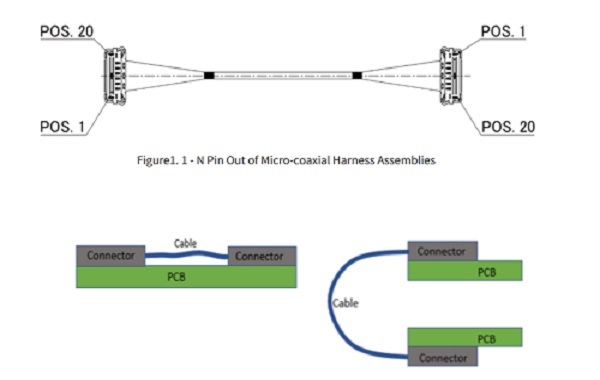
In the 1-N configuration, the first pin (Pin 1) at one end of the cable is connected to the Nth pin (Pin N) at the other end, ensuring that each micro coaxial cable within the cable is connected in a straight line without crossing, thereby improving assembly efficiency and simplifying the wiring structure. To achieve this configuration, the PCB or connector pin frame at both ends of the cable typically needs to be rotated relative to each other by 180 degrees to mirror the signal pin positions. This method is very suitable for board-to-board or chip-to-chip interconnections with mirrored layouts, without the need to add additional routing layers or multiple vias, simplifying the signal layout design within the board.
Main advantages:
Board-to-board or chip-to-chip connections suitable for mirror layouts
Avoid signal crossover within harnesses, improve signal integrity
• Reduce PCB wiring complexity, minimize the number of wiring layers and vias
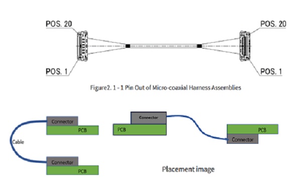
Type 1-1 (corresponding pin definition)
In the 1-1 configuration, the first pin (Pin 1) at both ends of the cable is directly connected to the first pin, with the other pins corresponding in order. This method is suitable for boards or chip interconnections with the same pin definition, with direct wiring and no need for signal exchange. The 1-1 cable ensures the symmetry of the signal path, simplifies the design, facilitates rapid assembly, and improves system stability.
Main advantages:
• Suitable for interconnection of devices or circuit boards with the same pin definition
Simplify harness design for quick assembly
Ensure signal path symmetry to enhance system stability
Three, application scenarios
1-N type cable harness is commonly used for interconnection between two circuit boards with relatively mirrored layouts, or for high-speed signal connections between mirrored chips on the same board; 1-1 type cable harness is suitable for board-to-board or chip-to-chip interconnections with the same pin layout. By selecting an appropriate pin definition method, design engineers can flexibly arrange signal paths according to specific layout requirements, avoid signal crossings, improve transmission integrity, and simplify PCB routing design.
Choosing the appropriate 1-N or 1-1 pin definition method for wiring harnesses can effectively enhance the integrity of high-speed signal transmission and system design efficiency. In high-speed electronic systems, scientific wiring harness design and precise pin definition are crucial for ensuring high reliability and high-performance interconnection.
I amSuzhou Huichengyuan Electronic TechnologyLong-term focus on the design and customization of high-speed cable harnesses and ultra-fine coaxial cable harnesses, committed to providing customers with stable and reliable high-speed interconnection solutions. For further information or customization, please contact:Manager Zhang 18913228573 (WeChat same number)。