


Categorization:Harness Component
In industrial cameras, machine vision, high-resolution cameras, AI vision equipment, and intelligent terminals, the MIPI interface undertakes the high-speed data transmission task between the image sensor and the processor. With the continuous improvement of camera resolution, frame rate, and image data volume, MIPI high-speed differential signals have put forward higher requirements for the impedance continuity, insertion loss, return loss, crosstalk, and EMI control of the transmission link. When engineers design high-speed Camera modules, if they still only focus on the chip and PCB itself and ignore the intermediate connecting cables, it is easy to encounter problems of declining link performance. Compared with ordinary ribbon cables, extremely thin coaxial cables adopt an independent coaxial transmission structure, where each signal path has a relatively independent shielding environment, which is more conducive to controlling the crosstalk between high-speed signals and external electromagnetic interference. At the same time, they can achieve high-density multi-channel wiring in a smaller space. Therefore, in high-speed MIPI applications, extremely thin coaxial cables are increasingly becoming an important cable scheme that takes into account high-speed transmission, miniaturization, and signal integrity.
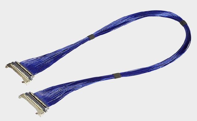
High-speed MIPI signals usually employ high-speed differential transmission, which is very sensitive to link impedance and signal integrity. When the cable structure is unreasonable, there is a significant change in impedance, or there is obvious crosstalk between adjacent high-speed channels, it may cause signal eye diagram contraction, increased jitter, and error rate increase. In severe cases, it may even lead to camera initialization failure, frame loss, or abnormal images. Extremely thin coaxial cables are composed of a central conductor, insulating layer, and shielding layer to form a relatively complete transmission channel. They can better control the electromagnetic field distribution during high-speed signal transmission. Taking the I-PEX 82988-100B-01-D product in this round as an example, the cable uses AWG#40, 50Ω Micro-Coaxial Cable, with a total of 60 pins and a length of 300MM, and connects in a 1-1 sequence. Compared with ordinary multi-core cables, this structure is more suitable for high-density high-speed signal transmission. At the same time, its matching cable end connector model is 20634-160T-02, which belongs to the CABLINE®-CA 60Pin connection scheme. The I-PEX CABLINE®-CA series uses a 0.4mm contact pitch, horizontal insertion, mechanical locking, shielding, and multi-point grounding design. According to the official data, this connector platform is for high-speed transmission applications up to 32 Gbps/Lane. Therefore, from the complete chain of "cable + connector + shielding + grounding," extremely thin coaxial cables can provide a more suitable connection foundation for high-speed MIPI systems.
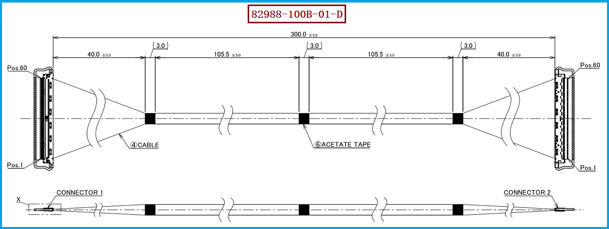
For engineers, a 300mm cable harness length means that it cannot be simply assumed that "as long as it conducts, it can be used." As the transmission distance increases, the insertion loss, return loss, impedance changes, and connector transition area effects on high-speed signals all need to be evaluated. Therefore, when designing high-speed MIPI applications using I-PEX 82988-100B-01-D, attention should be paid to the matching relationship between the 60Pin, AWG#40, 50Ω, 300MM, 1-1 wiring sequence, and 20634-160T-02 connector, and a systematic SI verification should be combined with the actual MIPI speed, Lane count, master PHY capability, and PCB routing. For purchasers, when selecting or seeking alternative cable harnesses, it is also not enough to compare only appearance, length, and price. Key parameters such as product material number/model, connector model, pin count, wire diameter, characteristic impedance, wiring sequence, length tolerance, and assembly structure should be checked. Especially in domestic substitution projects, even if the connector can be mechanically mated, it does not mean that the high-speed performance is completely consistent. Therefore, it is recommended to conduct TDR, VNA, insertion loss, return loss, crosstalk, and actual MIPI equipment joint debugging tests at the sample stage to confirm the high-speed transmission capability of the alternative cable harness under real working conditions.
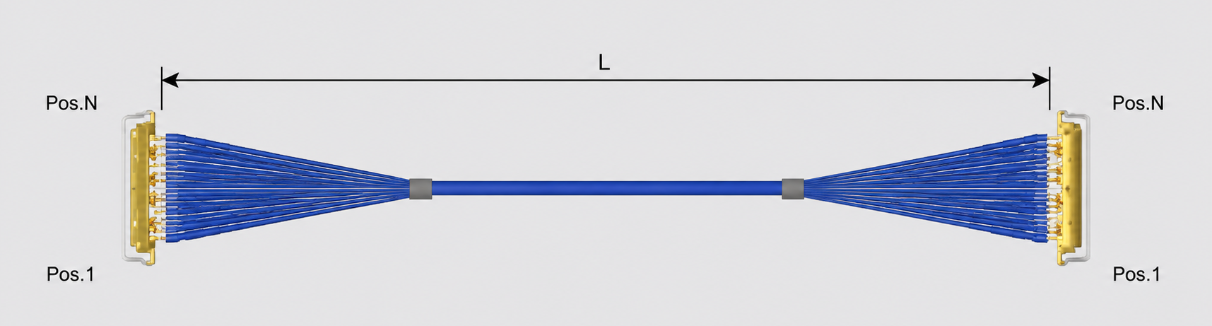
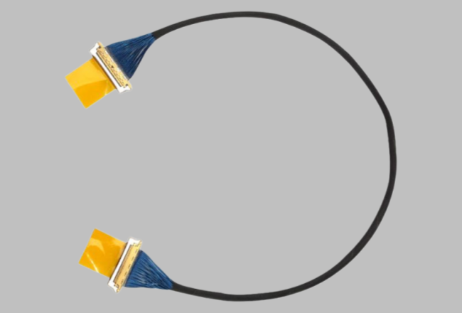
If the project originally used the I-PEX CABLINE®-CA series 60Pin ultra-thin coaxial cable assembly, then the I-PEX 82988-100B-01-D can be a very clear engineering reference model. The core specifications of this product are 60Pin, AWG#40, 50Ω, 300MM, 1-1, and the connector model used at the cable end is 20634-160T-02. When carrying out compatibility and alternative selection, it is recommended to first confirm the PCB end matching connector and Footprint, and then compare each item according to the connector pin count, cable specifications, impedance, wire sequence, and length, followed by high-speed signal integrity testing. If the actual application is the Sony IMX image sensor's MIPI CSI-2 high-speed link, it is also necessary to combine the specific sensor model, MIPI Lane configuration, and actual data rate for final verification, and cannot be directly determined as compatible based solely on the term "MIPI interface". In terms of the original factory cable procurement cost, lead time, supply chain stability, and the demand for domestic substitution, our company can provide: I-PEX 82988-100B-01-D compatible alternative cable solution, which can develop, prototype, and match specifications for ultra-thin coaxial cable assembly around the product's 60Pin, AWG#40, 50Ω, 300MM, and corresponding connector structure, providing high-speed application verification support for engineers, as well as a reference for purchasing personnel on second supplier and domestic substitution solutions.
“Without the consent or authorization of this site, no one shall reproduce, reprint, distribute, cite, change, broadcast or publish the content in whole or in part in any form, nor shall there be any other violation of the copyright of this site.