Categorization:Harness Component
Part 1: Transmission Characteristics of D-PHY and C-PHY
D-PHY uses differential signal transmission, where each pair of signal lines transmits data through voltage difference, with typical rates reaching 1.5Gbps to 4.5Gbps and is widely used in camera interfaces (CSI) and display interfaces (DSI). C-PHY, on the other hand, uses a three-wire system for transmission, with each group of three wires transmitting data together, achieving higher data throughput at the same bandwidth, for example, the equivalent rate of C-PHY v1.2 can reach 13Gbps. Different signal structures determine the束 design strategies and the focus of transmission performance.
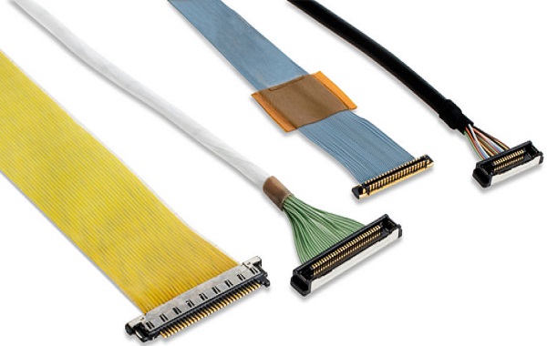
Design Considerations for Ultra-fine Coaxial Cable Assemblies
Due to the different signal forms of D-PHY and C-PHY, the cable design needs to be optimized specifically. D-PHY emphasizes differential impedance control, usually requiring 100Ω±10%, so the cable selection must ensure a single-line impedance of about 50Ω. C-PHY pays more attention to the geometric symmetry and phase consistency among the three lines to ensure efficient data transmission. In high-speed applications, extremely thin coaxial cables can reduce crosstalk through independent shielding and precise structure, and multi-layer shielding structures can further enhance signal stability. In addition, due to the limited space in mobile devices, the cable must also consider flexibility and bend life, especially for the three-line combination of C-PHY, which puts higher requirements on termination and processing technology.
Connectors and Harness Matching
In actual assembly, the match between the connector and the harness directly affects signal integrity. D-PHY mostly uses traditional differential interfaces, such as Hirose or I-PEX connectors; C-PHY usually requires a customized three-wire interface. Asymmetrical interface layout or uneven welding points can cause reflections and signal distortion. Therefore, the harness manufacturer needs to work with the whole machine designer at the early stage of the project to determine the wire diameter, shielding structure, and termination layout together, ensuring overall impedance continuity and stable transmission of high-frequency signals.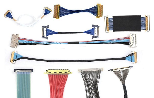
“Without the consent or authorization of this site, no one shall reproduce, reprint, distribute, cite, change, broadcast or publish the content in whole or in part in any form, nor shall there be any other violation of the copyright of this site.