Categorization:Harness Component

The main consequences of impedance mismatch
Impedance discontinuity can have various effects on high-speed signals. Firstly, signal reflection and eye diagram closure can lead to waveform distortion, especially for high-speed interfaces such as MIPI D-PHY, LVDS, USB 3.x, and DisplayPort. Secondly, impedance mismatch can exacerbate EMI/EMC issues, with common-mode interference and crosstalk in multi-core cables amplified, affecting the electromagnetic compatibility of the system. Finally, it can also cause transmission delay and amplitude attenuation, with inconsistent signal arrival times (skew), which may lead to screen flickering or frame errors, particularly in high-speed camera or display applications.
Two, common causes of impedance mismatch
Impedance mismatch usually originates from the design and assembly stages. Firstly, improper coaxial structure design, such as deviation in conductor diameter, medium thickness, or shielding density, will directly change the characteristic impedance. Secondly, machining and assembly errors, such as excessive crimping, welding, or stripping, will also disrupt geometric consistency. Thirdly, mismatched connector selection, with some miniature connectors (such as Hirose, I-PEX series) having high impedance tolerance requirements. Lastly, design flaws in PCB terminal matching network, such as inaccurate termination resistors or poor trace transitions, can also lead to overall impedance discontinuity.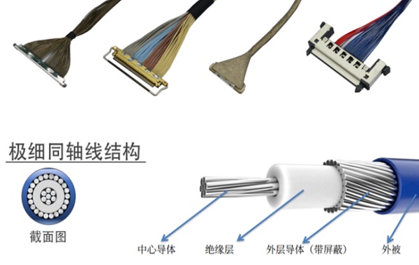
Three, effective strategies for impedance matching
To solve impedance mismatch, optimization should be carried out throughout the entire process from design to testing. Firstly, maintain consistency in the harness structure, strictly control the dimensions of conductors, media, and shielding, and verify the impedance continuity at the sample stage through TDR testing. Secondly, choose matching high-precision connectors, optimize the termination length and crimp depth, and adopt stepped welding structures when necessary. Thirdly, on the PCB side, achieve consistency with the cable impedance by controlling the trace width, media thickness, and differential spacing, and add terminal matching resistors. Finally, through multi-layer shielding, 360° grounding, and testing verification of the closed loop, reduce common-mode interference, and ensure signal integrity.
“Without the consent or authorization of this site, no one shall reproduce, reprint, distribute, cite, change, broadcast or publish the content in whole or in part in any form, nor shall there be any other violation of the copyright of this site.